![]()
![]()

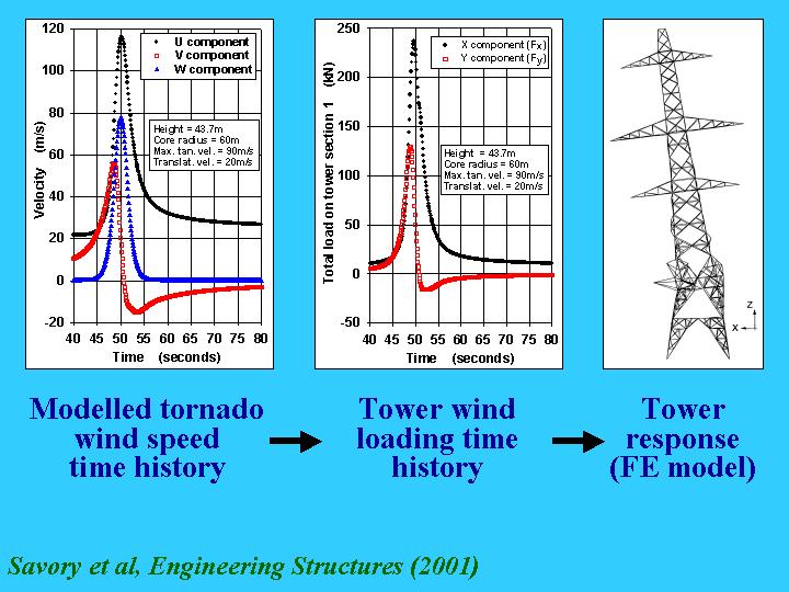
FAILURE OF TRANSMISSION LINES DUE TO HIGH INTENSITY WINDS (Collaborative project: UWO and University of Surrey, UK)
The structures of tornadoes and microbursts are being investigated, together with the manner in which they interact with transmission line systems to cause failure. The work involves development of simple empirical models for the wind field, followed by more advanced Computational Fluid Dynamics codes for application to a Finite Element structural analysis model. Some preliminary results have been published. Click here for full paper
Acknowledgements: Funding from Manitoba Hydro, Dr P Yu, Dr D Surry, D H Hangan, Dr E Ho, Dr G Parke, Dr P Disney, Mr P Roberts, Prof N Toy
WIND - INDUCED FOUNDATION LOADS ON A TRANSMISSION TOWER
The action of the wind represents a significant part of the loading on a typical high-voltage transmission line supported by lattice towers. Research carried out in the field in the United Kingdom has been focused on assessing the wind - induced foundation loads on a National Grid Company L6 tower located in the South West of England, with a view to assessing the reliability of existing design data.
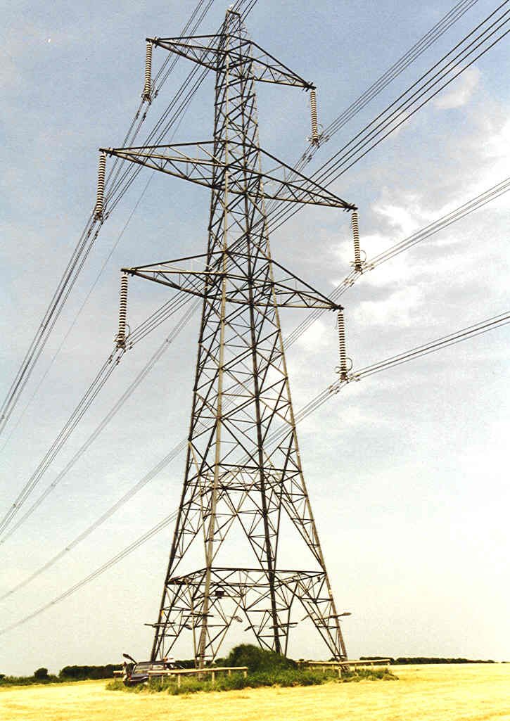
A typical L6 transmission line tower
The four tower legs were instrumented with strain gauge arrays, suitably weather - protected, and the data from these were logged, together with the wind speed measured at the top of the tower.
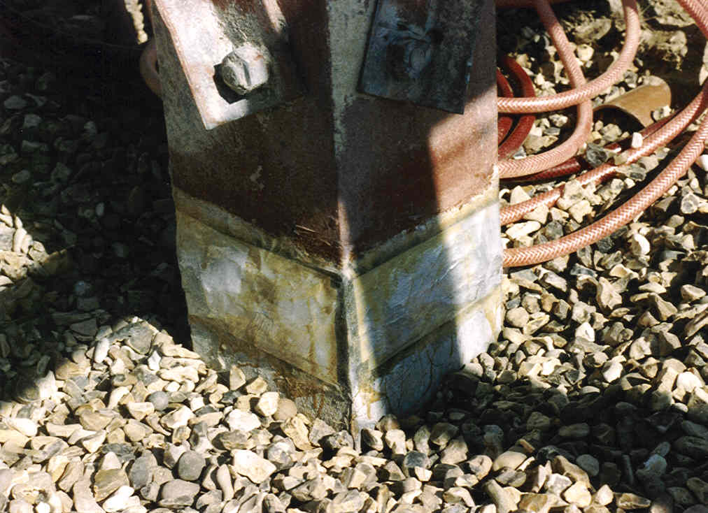
Weather - protected strain gauge array on leg angle section immediately above the foundation
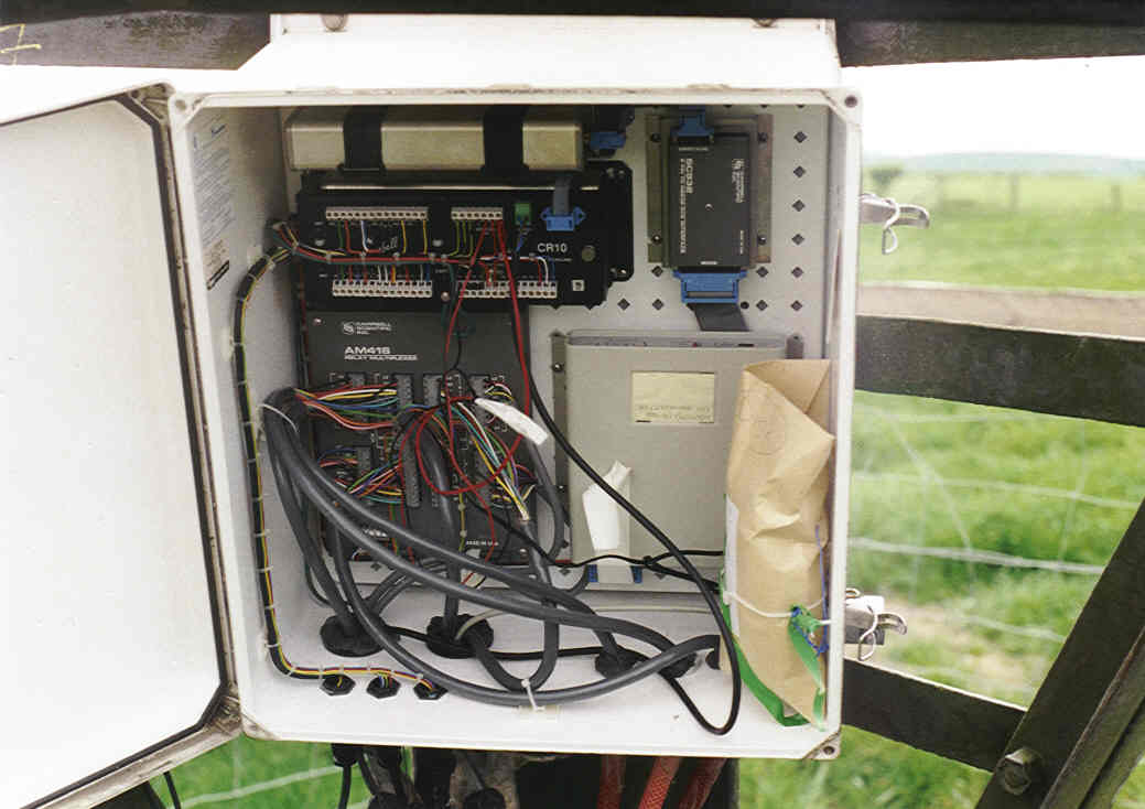
Data - logger in weather resistant enclosure
Data were obtained over a five year monitoring period, with the distributions of wind directions showing the expected predominance of South Westerly and North Westerly winds.
Site wind rose
For each five degree band of wind direction the relationship between the measured strain in each tower leg and the square of the wind speed was derived, using the complete data set.
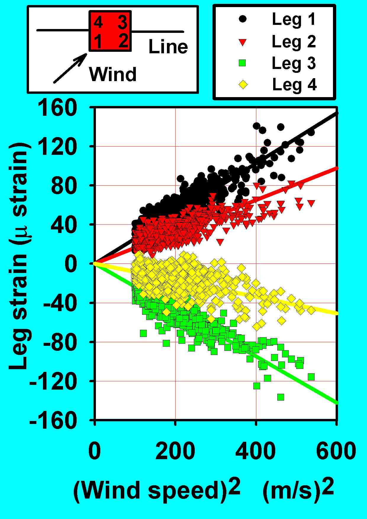
Relationship between the strain in each of the tower legs and the square of the wind speed for a wind direction of 225 degrees measured from the normal to the transmission line (for wind speeds above 10 m/s)
The linear relationship obtained allowed the derivation of a general plot encompassing the loads in the four legs for all of the wind directions, as shown below.
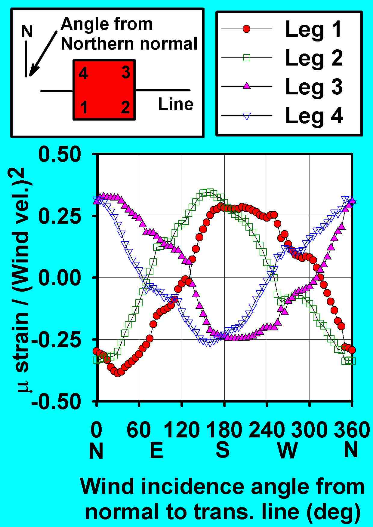
Variation of tower Leg Strain / (Wind Speed)2 for all four legs with wind incidence angle measured from the normal to the transmission line
In the UK the principal Code of Practice for lattice tower design is British Standards BS 8100. The Code's provisions for the wind loading on the conductors, earth wire, insulators and tower members, were analysed to produce a generalised formulation of Leg Strain / (Wind Speed)2, for comparison with the field data. The plot derived is shown below.
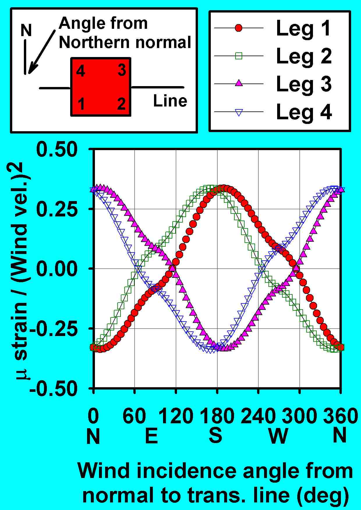
Code calculation of the variation of tower Leg Strain / (Wind Speed)2 for all four legs with wind incidence angle measured from the normal to the line
Bringing all of the data together in the following scatter plot reveals that the Code of Practice provides a very good indication of the wind - induced foundation loadings that may be expected to occur on a transmission tower for any given wind speed and direction. The regression data show a slope of 1.0102 (that is an agreement of within approximately 1%) with a correlation coefficient of R = 0.965.
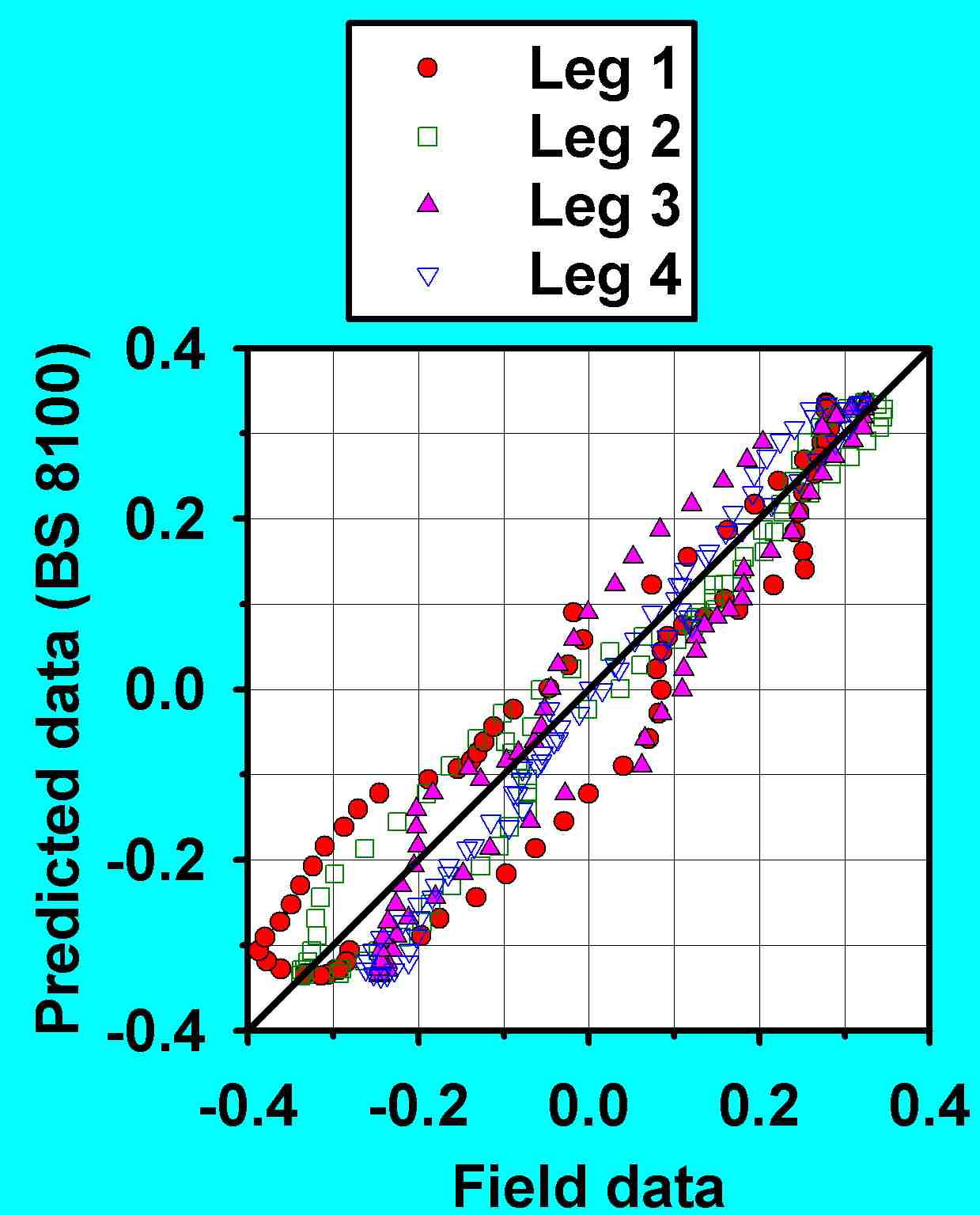
Comparison of field data and Code calculations for Leg Strain/(Wind Speed)2
Acknowledgements: This project was funded by the National Grid Company Plc (UK). The work was also conducted by Dr G A R Parke (PI), Dr P Disney and Prof N Toy.